

Hauler & Hermann
Back to knowledge
Technical Insight

Stator Winding Insulation: Every Part from Slot Base to End Winding

Yannick Wille

By Yannick Wille, Managing Director

October 20, 2026

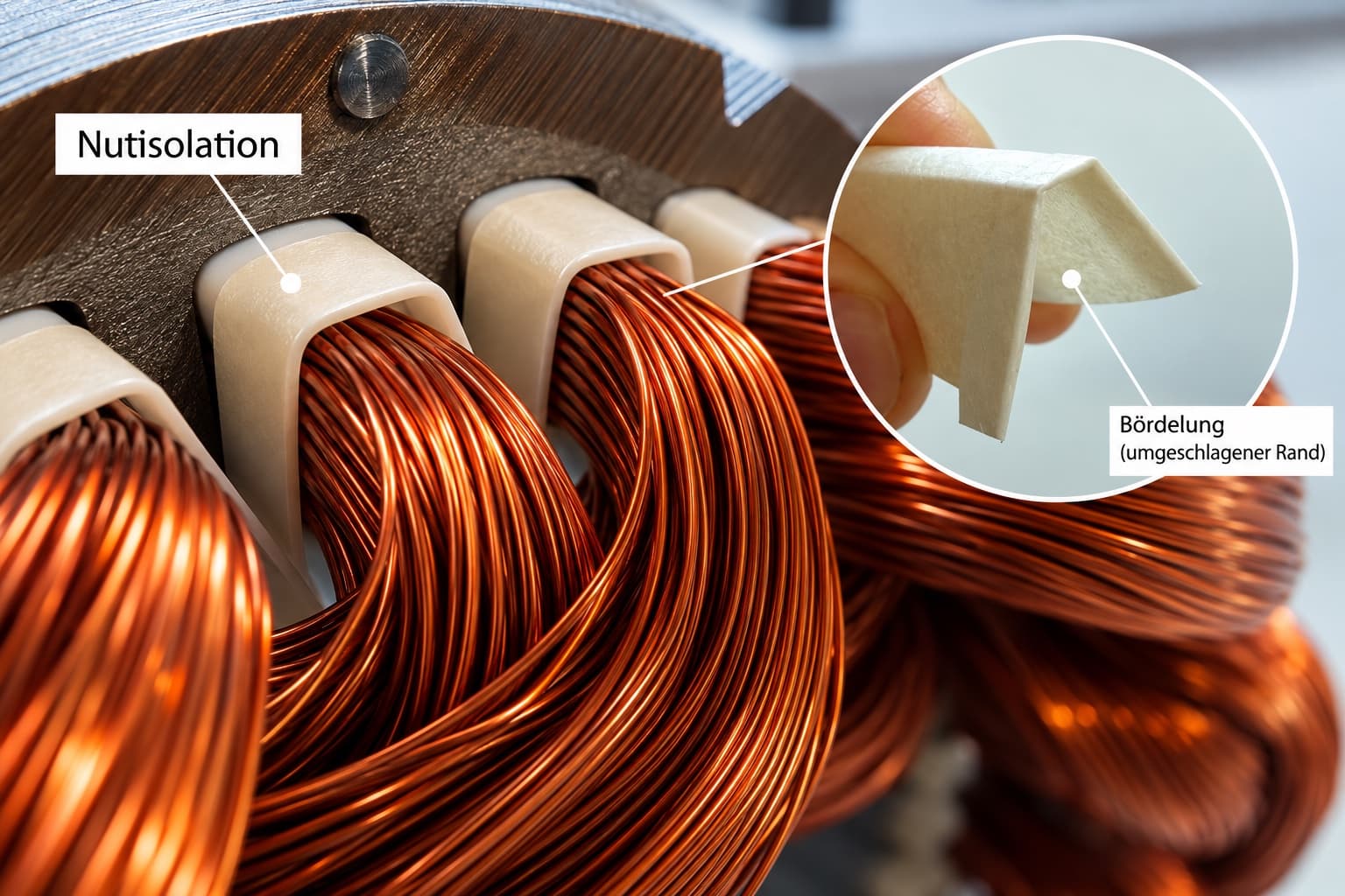
Stator with round wire winding, slot liners protruding from the slots, inset showing the folded cuff

The stator winding is the copper winding in the stationary part of an electric motor or generator. It sits in the slots of the lamination stack. In a motor it creates the rotating magnetic field, in a generator the voltage is induced in it. For this to work reliably, the copper must be insulated from the lamination stack and from the other phases at every point.

A stator winding is therefore more than copper. Between wire and lamination stack, between winding layers and between phases sit insulation parts, each with its own job. If one of them is out of place, an insulation failure in operation is a real risk: an earth fault between winding and core, or a phase-to-phase fault.

This article is written for design engineers and buyers at motor manufacturers and for rewinding shops. It walks through a conventional round wire winding step by step, from the slot base to the end winding, and shows where our customers see the most problems. Each part links to a more detailed article. If you are overhauling an existing motor, read when rewinding a motor pays off for what is different in repair work.

Slot liner: the first layer at the slot base

It starts with the slot liner, also called slot insulation, slot paper or slot cell insulation. It is inserted into the slot of the lamination stack before winding and separates the copper wire from the stator core. Depending on the design it is cuffed, meaning the edges at both ends are folded over, or uncuffed.

The round wire is then wound into the insulated slot. The aim is to fill the slot cross-section with as much copper as possible. The slot liner should therefore be as thin as possible while still providing the dielectric strength the application requires and surviving coil insertion undamaged. Where that trade-off lies, and what changes in hairpin stators, is covered in how thin a slot liner can be.

At the end faces the slot liner usually protrudes beyond the lamination stack. How far depends on the required creepage distance, the path along the insulation surface from the winding to the core. Which dimensions belong on the drawing is explained in creepage distances and clearances on the drawing.

“A critical point is often the slot liner. It has to sit very precisely in the slot.”

Yannick Wille, Managing Director

Slot separator: isolating the winding layers

Depending on the winding design, a slot holds two winding sections on top of or next to each other. A slot separator isolates them electrically and adds mechanical stability.

In double-layer windings it sits between the two layers, often as a U-profile, and often protrudes beyond the lamination stack at both ends. In concentrated (tooth) windings, where each coil is wound around a single stator tooth, a Z-profile separates the two neighbouring coils in the middle of the slot. Thin, flexible laminates are typical, for example NPN at 0.17 to 0.22 mm. Which profile fits when is the subject of U- and Z-profile separators for double-layer and concentrated windings.

Slot closure and slot wedge: sealing the slot

Once the winding is complete, a slot closure closes the slot at the top. Among other things it keeps the wire from working its way back out of the slot.

Depending on the design, a cover strip or a slot wedge is added to secure the assembly mechanically. Some designs use both: first the slot closure over the winding, then the wedge that locks into the slot opening. There is no fixed machine size at which wedges take over. They are most common in generators and high-voltage machines. Wedge geometries, materials and the case-by-case decision are covered in when a slot closure is enough and when a wedge is needed.

Phase separators: phase insulation in the end winding

Outside the slot lies the end winding, where the winding sections of the individual phases pass each other. Phase separators isolate them electrically and so prevent a phase-to-phase fault. They are flat die-cut parts whose contour is matched to the end winding, especially in the curves.

They are often made from DMD laminate or from NPN based on Nomex® 411. This aramid paper is uncalendered and has an open, fibrous surface that absorbs resin well during the subsequent impregnation.

Where most problems occur in practice

A frequent critical point is the slot liner. If it does not sit precisely in the slot, the wire can get between the slot liner and the stator core during winding. This fault, known as winding behind the liner, can later cause an earth fault between winding and core and must be prevented at all costs.

Second, the wire being pulled in can drag the slot liner along and shift it. The cuff prevents this: the folded edge holds the insulation in position.

Third, the slot closure. If the slot still has too much play, the slot closure does not sit tightly enough and can slip. An additional mechanical lock such as a slot wedge is then needed.

The phase separator, by contrast, is rarely the problem. It becomes demanding on automated lines, because a flat, flexible die-cut part is hard to singulate and orient from bulk. There the supply format decides, see supply formats for phase separators on automated lines.

“The phase separator itself is usually not one of the most critical insulation parts in a motor. Problems occur more often with the slot liner or the slot closure.”

Yannick Wille, Managing Director

Large generators: a different insulation system

Large generators and high-voltage machines use preformed form-wound coils or Roebel bars instead of round wire. They are insulated before insertion, for example taped with mica tapes, and then placed in the slot. Copper cross-section, taping, slot insulation and slot geometry are matched as one high-voltage insulation system. The details are in how Roebel bars and form-wound coils are insulated, and the matching parts are on the generators page.

“Insulation in large generators is therefore not simply a single component, but a matched high-voltage insulation system whose exact design is specified by the machine manufacturer.”

Yannick Wille, Managing Director

All insulation parts for one stator from one source

As the motor or generator manufacturer, you specify the stator winding design, including material thicknesses, overhangs and distances. We produce every part of it to your drawing, from the slot liner to the phase separator. On request we supply the parts for a stator as a kit pack, put together in exactly the quantity you need per stator. An overview of all parts for motor manufacturers is on the insulation parts for electric motor manufacturing page.

Do you have a specific requirement?

Talk to us. We will find the right insulation solution.

Frequently asked questions

Which insulation parts are in a stator winding?

A stator winding has a slot liner in each slot, a slot separator depending on the winding, the slot closure on top and, depending on the design, a cover strip or slot wedge. In the end winding, phase separators isolate the individual phases.

What is winding behind the slot liner?

Winding behind the slot liner means the wire gets between the slot liner and the stator core during winding. It happens when the slot liner does not sit precisely in the slot, and it can later cause an earth fault between winding and core. An accurately fitting slot liner prevents it.

What is the folded edge of a slot liner called?

The folded edge is called the cuff, and a liner with it is a cuffed slot liner. It stops the wire being pulled in from dragging the liner along during winding, and its geometry helps maintain the required creepage distance. Cuffed and uncuffed designs are on the slot liner product page.

In what order are the insulation parts fitted in a stator?

The slot liner goes into the empty slot first, then the winding is wound in. In double-layer windings the slot separator lies between the bottom and top layer. Phase separators in the end winding are placed during coil insertion, after the coils of each phase. After winding, the slot closure closes the slot, secured by a slot wedge depending on the design. When the wedge becomes necessary is covered in slot closure and wedge compared.

What is the difference between an earth fault and a phase-to-phase fault?

An earth fault is a fault between the winding and the lamination stack, a phase-to-phase fault one between two phases of the winding. Slot liner and slot closure mainly protect against earth faults, while slot separators between layers of different phases and phase separators in the end winding protect against phase-to-phase faults. How phase separators reach automated lines is covered in phase separators in the end winding.