

Hauler & Hermann
Back to knowledge
Technical Insight

Double-Layer and Concentrated Windings: U- or Z-Profile Slot Separators

Yannick Wille

By Yannick Wille, Managing Director

November 10, 2026

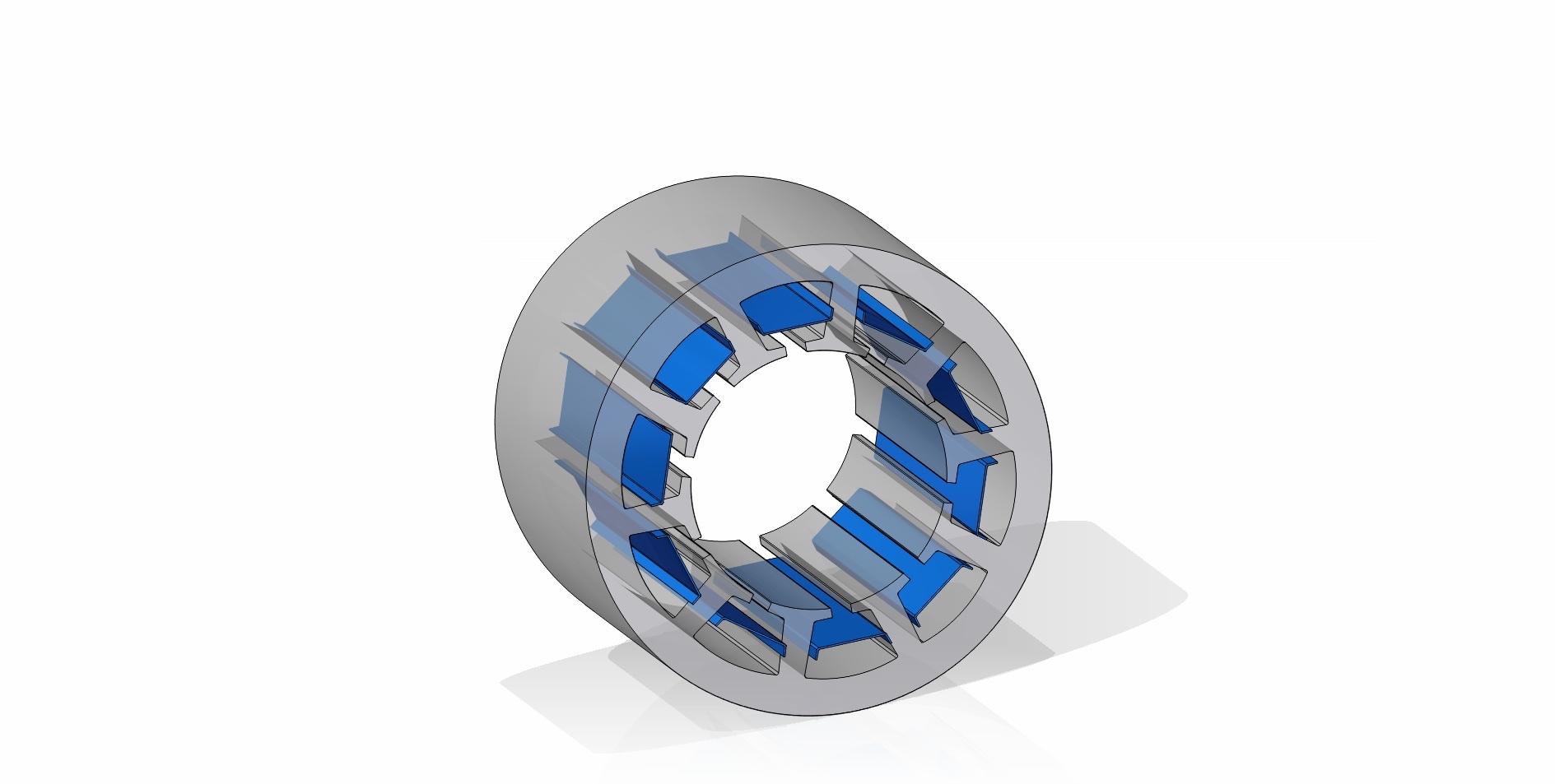
3D render of a grey stator ring with blue insulation profiles as slot separators in the slots, on a white background

A double-layer winding is a winding in which every slot holds two coil sides on top of each other, one in the bottom layer and one in the top layer. Because the two layers belong to different coils and often to different phases, they have to be insulated from each other inside the slot. This is the job of the slot separator, also called interlayer insulation, a thin insulation profile between the two layers.

This article explains how double-layer and single-layer windings differ, which two designs of slot separator exist and which material and thickness are typical. The focus is the winding technology behind the part: why the layers are separated, where and in which form. It is written for design engineers who specify a slot separator and for buyers who source it. Where the separator fits into the overall build-up is shown in the overview of which insulation parts sit in a stator.

Single-layer vs double-layer winding: what is the difference?

In a single-layer winding one coil side fills the entire slot, in a double-layer winding two coil sides share the slot. A single-layer winding therefore needs half as many coils as there are slots, while a double-layer winding has as many coils as slots.

The advantage of the double-layer design is freedom in the coil span. It can be made shorter than the pole pitch (short pitching or chording), which damps harmonics in the air-gap field and shortens the end windings. Double-layer windings also allow fractional-slot windings, in which the number of slots per pole and phase is not a whole number. The consequence for insulation: in a short-pitched winding, some slots carry coil sides of different phases on top of each other. The voltage between top and bottom layer can then reach the full line-to-line voltage.

In a single-layer winding each slot belongs to exactly one phase, so no insulation between two layers is needed inside the slot. The phases only meet outside the slot, where, as in any distributed three-phase winding, phase separators in the end winding keep them apart.

Slot separators in double-layer windings: often a U-profile

In a conventional double-layer winding, a slot separator, often shaped as a U-profile, divides the bottom layer from the top layer. The profile resembles a slot closure, but instead of sitting at the slot opening it sits deeper in the slot, between the two winding layers. Flat interlayers are also common in double-layer windings.

The sequence in the slot is therefore fixed: slot liner, bottom layer, slot separator, top layer, slot closure. Depending on the process, the separator is pushed in axially or placed during coil insertion, and it has to keep the layers cleanly apart through insertion, forming and impregnation. Separators of this design are often longer than the lamination stack and protrude at both ends. How the slot is then closed is covered in slot closures compared with slot wedges.

Concentrated windings: Z-profile slot separators

In a concentrated winding, also called a tooth-coil winding, each coil is wound around a single stator tooth. If every tooth carries a coil, each slot holds the coil sides of two neighbouring coils side by side, often belonging to different phases. In winding terms this is also a double-layer winding, with the two layers side by side.

The dividing line therefore runs along the depth of the slot rather than across it. This is where the Z-profile slot separator is used. It splits the slot into a left and a right half, and its angled legs give it a firm hold.

“The Z-profile sits roughly in the middle of the slot and separates the two neighbouring windings vertically. The Z geometry allows the insulation between the two winding sections to be positioned precisely and held mechanically in the slot.”

Yannick Wille, Managing Director

Which material and thickness for slot separators?

Slot separators are usually made from thin, flexible insulation laminates. A typical material in our practice is NPN laminate grade NPN/50 at 0.17 to 0.22 mm. NPN consists of two layers of Nomex® aramid paper with a polyester film in between, and the number 50 stands for Nomex outer layers of 50 µm. The laminate is rated thermal class F (155 °C).

Depending on thermal class and the voltage between the layers, DMD laminate, Nomex 410 aramid paper or Mylar® polyester film are also options, covering materials from class B to H. The exact thickness follows from the electrical design and the space available in the slot. Every tenth of a millimetre the separator takes up is lost to copper, which is why it is usually thinner than the slot closure in the same slot. The effect on the copper in the slot is explored in the article on slot fill factor and slot liner thickness.

“Especially with the slot separator, the aim is to achieve the necessary electrical separation without taking up unnecessary space inside the slot.”

Yannick Wille, Managing Director

How a U- or Z-profile slot separator is made

A slot separator starts as a flat web of insulation laminate. Flat slot separators are simply cut to length, while folding and forming shapes the web into the U- or Z-profile, for the U-profile including the overhang beyond the lamination stack. The skill lies in creasing the thin laminate sharply enough for the profile to hold in the slot without damaging the material.

“Which design is required ultimately depends on the winding type and the slot geometry of the motor. The specific geometry is specified by the customer and manufactured by us accordingly.”

Yannick Wille, Managing Director

Specifying a slot separator: what the drawing needs

A slot separator drawing needs six details. First, the winding type: double-layer winding with top and bottom layer, or concentrated winding with coils side by side. This determines whether a U- or a Z-profile is required. Second, the slot geometry including the position of the separator in the slot. Third, the core length and the overhang at both ends. Fourth, the thermal class and material, fifth, the material thickness. Sixth, the quantity and packaging, for example as a set with slot liner and slot closure per stator.

The overhang is not a margin added by feel, it follows from the creepage distances and clearances of the winding. What that means for the drawing is explained in how creepage distances and clearances set the overhang. Designs, materials and supply options are summarised on the slot separator product page.

Do you have a specific requirement?

Talk to us. We will find the right insulation solution.

Frequently asked questions

What is a double-layer winding?

A double-layer winding is a winding with two coil sides per slot, one in the bottom layer and one in the top layer. It has as many coils as slots and allows a shortened coil span (short pitching). Because top and bottom layer can belong to different phases, a slot separator divides the two layers.

What is the difference between single-layer and double-layer windings?

In a single-layer winding one coil side occupies the whole slot, in a double-layer winding two coil sides lie on top of each other. A single-layer winding therefore needs no slot separator inside the slot, while a double-layer winding usually does.

What is a concentrated winding?

A concentrated winding, also called a tooth-coil winding, is a winding in which each coil is wound around a single stator tooth. If every tooth carries a coil, each slot holds two coil sides side by side, often from different phases. A Z-profile slot separator keeps them apart.

What is the difference between U-profile and Z-profile slot separators?

The U-profile divides the bottom layer from the top layer in a double-layer winding, so it lies across the slot between two stacked layers. The Z-profile separates two side-by-side coils vertically in a concentrated winding, roughly in the middle of the slot. The right design follows from the winding type and the slot geometry.

How thick is a slot separator?

Thin, flexible laminates are typical, for example NPN/50 at 0.17 to 0.22 mm. The exact thickness follows from the electrical design and the space available in the slot. The goal is the required separation with as little copper space lost as possible.