Hauler & Hermann
Back to knowledge
Technical Insight

Creepage vs Clearance in Electric Motors: Difference and Drawing Dimensions

Yannick Wille

By Yannick Wille, Managing Director

November 03, 2026

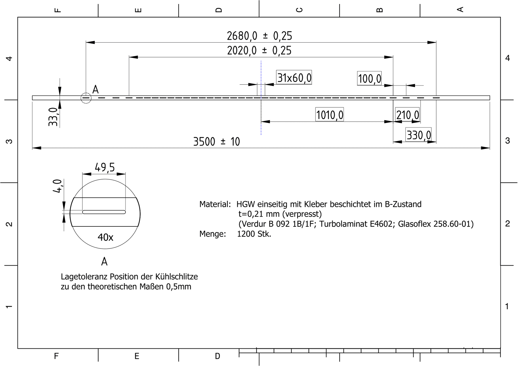
Technical drawing of an insulation part with dimensions, tolerances and material specification as the basis for production

Clearance is the shortest distance through air between two conductive parts, creepage distance is the shortest distance along the surface of an insulating material between the same parts. Clearance prevents flashover through air. Creepage distance is sized so that no continuous conductive tracking path can form on a damp or contaminated insulation surface.

In an electric motor, both distances end up as specific dimensions on insulation parts, above all the overhang of the slot liner beyond the lamination stack. This article is for design engineers and buyers. It explains the difference, the influencing factors and the critical points in the stator, and shows which dimensions therefore belong on the drawing for an insulation part.

Creepage vs clearance: the difference

Creepage and clearance differ in their path, in the voltage they are sized for and in the way they fail. Clearance measures the direct path through air, creepage distance the path along the surface of an insulating material. Geometrically, the creepage distance is therefore never shorter than the clearance between the same two parts. Every edge, fold and overhang the surface path has to go around makes it longer.

Clearance is sized for the voltage peaks that can occur, that is impulse voltages and transient overvoltages. If it is too short, the air breaks down instantly. Creepage distance is sized for the RMS value of the voltage that is permanently applied. It does not fail suddenly but over time: moisture and deposits allow leakage currents to flow, which damage the surface step by step until a conductive path forms.

What determines the required creepage distance and clearance

The required clearance depends mainly on the impulse voltage it has to withstand. Pollution degree, the shape of the electric field and altitude also play a part. The dielectric strength of air falls as air density falls, so clearances have to be increased for installation altitudes above 2,000 m.

The required creepage distance depends on three factors: the working voltage, the pollution degree and the material. The pollution degree describes in four levels what to expect at the installation site, from no pollution or only dry, non-conductive pollution (degree 1) to persistent conductive pollution (degree 4). How well an insulating material resists tracking is described by its tracking resistance, given on the data sheet as the CTI (Comparative Tracking Index). On this basis, insulating materials are classified into material groups, from group I with a CTI of 600 or more down to group IIIb. The more tracking-resistant the material, the shorter the creepage distance may be under otherwise equal conditions.

The basics are set out in the standard on insulation coordination for equipment within low-voltage supply systems, IEC 60664-1 (EN 60664-1 in Europe). It covers equipment up to 1,000 V AC or 1,500 V DC, and high-voltage machines follow other rules. The specific values for a machine are set by the product standards that apply to it. For motors in hazardous areas with increased safety protection, for example, IEC 60079-7 sets its own minimum values, and for motors in household appliances IEC 60335-1 does.


Creepage distance in electric motors: slot liner overhang and other critical points

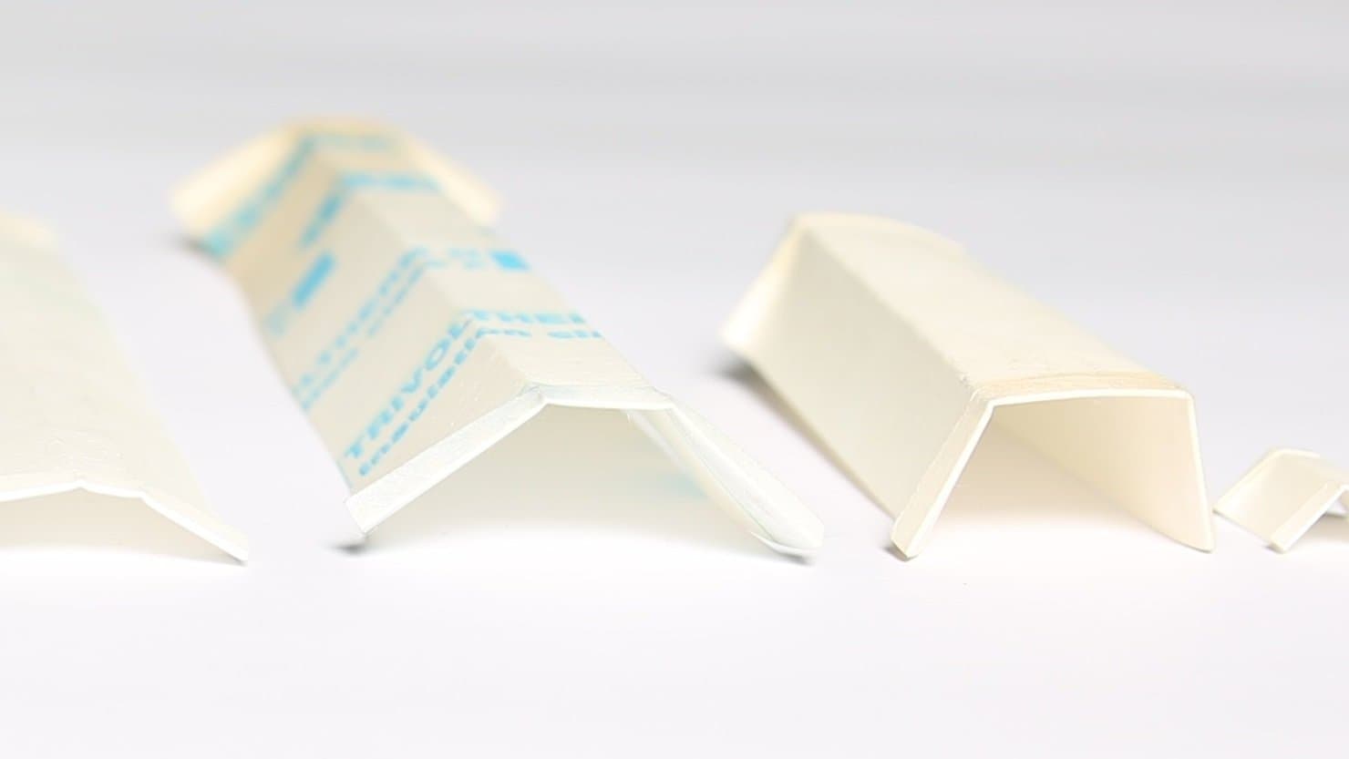
A key creepage distance in the stator lies at the slot end, where the winding leaves the lamination stack. If the slot liner protrudes beyond the stack there, the surface path from the winding to the core has to go around this overhang. The longer the overhang, the longer the creepage distance. The cuff, a folded edge on the slot liner, works in the same direction: its geometry helps maintain the required creepage distance, and it keeps the liner in place during winding.

The thickness of the slot liner, by contrast, adds little to the creepage distance. It determines the dielectric strength through the material and competes there with the copper share in the slot, as explained in how thin a slot liner can be.

Between two winding layers in the same slot, the slot separator provides the separation. It is often longer than the lamination stack and protrudes at the ends, so the separation extends beyond the slot. More on this under when a slot separator is needed. In the end winding, the phases pass close to each other outside the slot. Flat die-cut parts matched to the end winding sit between them, see fitting and supplying phase separators. Which part sits where in the stator is shown in the overview of all stator winding insulation parts.

Folded slot liners in different profiles and sizes: length and overhang are set by the customer drawing

Who sets creepage and clearance on an insulation part?

Creepage and clearance are set by the manufacturer of the motor or generator during design, because only the machine builder knows the voltage, insulation concept, operating environment and applicable standards. The result is not a set of distances on paper but dimensions: length and overhang of the slot liner, length of the slot separator, dimensions of slot closure and phase separator. These dimensions are on the technical drawing, and the drawing is the document every delivery can be measured against. Our part is to produce length, overhang and cuff exactly as they appear there.

“We at Hauler & Hermann do not set these distances ourselves. Our customers develop and design the motor or generator and are responsible for taking the required clearances and creepage distances into account in the design.”

Yannick Wille, Managing Director

Checklist: what belongs on the drawing for an insulation part

A drawing that can be produced from without further questions starts with the geometry: length, width or developed width, profile and leg lengths, for slot liners the slot geometry including any skew, and for a slot closure the back width and leg length.

Next come the dimensions that carry your creepage and clearance: the slot liner overhang at both ends, the length of slot separator and slot closure, design and size of the cuff, and the contour of the phase separators. State the stack length as well, so every overhang has a clear reference.

Add tolerances, above all for every dimension that governs a distance, and the material with grade and thickness, for example NPN, DMD or Nomex® 410. If tracking resistance is part of your design, specify the material itself and not just the thermal class, because two materials of the same thermal class can differ in CTI. Finally, quantities and supply form: lengths, rolls or finished die-cut and formed parts.

“The resulting geometries and dimensions are defined by the customer in a technical drawing. It specifies, for example, how long a slot liner must be, which overhangs are intended or which dimensions a slot closure or other insulation part must have.”

Yannick Wille, Managing Director

From drawing dimension to verified part

A creepage distance that is correct on the drawing only helps if the part holds the dimensions. Overhangs, cuff and lengths that are clearly dimensioned and toleranced give you insulation parts that can be checked against the drawing with every delivery. The insulation parts we make for motors are listed on the electric motor manufacturing page.

Do you have a specific requirement?

Talk to us. We will find the right insulation solution.

Frequently asked questions

What is the difference between creepage distance and clearance?

Clearance is the shortest distance through air between two conductive parts, creepage distance the shortest distance along the surface of an insulating material. Clearance is sized for impulse voltages and overvoltages and protects against flashover, creepage distance is sized for the permanently applied voltage and protects against a conductive tracking path on the surface. Between the same parts, the creepage distance is never shorter than the clearance.

Who sets the creepage distance for an insulation part?

The creepage distance is set by the manufacturer of the motor or generator when designing the machine. They translate it into dimensions such as slot liner length and overhang and specify these on the technical drawing that the insulation parts manufacturer produces to.

What does the required creepage distance depend on?

The required creepage distance depends on the voltage, the pollution degree of the environment and the tracking resistance of the insulating material, given as the CTI value. IEC 60664-1, the basic standard for low-voltage equipment, classifies insulating materials into material groups on this basis, from group I with a CTI of 600 or more down to group IIIb. The higher the tracking resistance, the shorter the creepage distance may be under otherwise equal conditions.

What does the overhang of a slot liner do?

The overhang lengthens the path along the insulation surface between winding and core, and with it the creepage distance at the slot end. A cuff has a similar effect and also stops the liner slipping during winding, as described on the slot liner page.

What needs to be on the drawing for an insulation part?

The drawing for an insulation part needs the geometry, all overhangs and lengths referenced to the stack length, tolerances for every dimension that governs a distance, the material with grade and thickness, and quantity and supply form. Only then can every delivery be checked clearly against your specification.